The Val Ease Central Railroad ©
Taking Z Scale to the Public Around the World
(Text and photos © Copyright Jeffrey MacHan)
Rewiring the Marklin Turntable for the Val Ease Central

The Märklin turntable wiring circuit.
Integrating the turntable into a viable track plan to be housed in a 30 by 21 inch hard shell suitcase was quite a challenge. Planning took the better part of 6 months, 2 months more than the original Val Ease West layout. Obstacles to overcome included how to wire the turntable for handheld control and how to fit a roundhouse into the suitcase. See the accompanying article for the solution to that challenge.
So what's the big deal about wiring a turntable you ask? Have you seen the instructions that come with it? Suffice to say that there is no electrical schematic of the control wiring.
What did I do?
I took the original control box apart and removed the bridge from the turntable to follow the wiring and document the circuitry. Doing this immediately voided any warranty that I might have enjoyed at the time but I was a daredevil in those days.
What did I learn?
1. the power inputs to the Marklin control box can be 10v AC or or 6-9v DC.
The polarity of the DC connection does not matter,
2. the gray lead from the box is DC to the turntable motor,
3. the yellow lead from the box is DC to power the solenoid that retracts the
turntable bridge alignment pin,
4. the blue lead is in series with a 9 ohm resistor and completes the DC to the turntable motor. Note that the blue wire in the diagram would normally plug into the green socket of the turntable,
5. the other two leads are DC track power to the turntable bridge track.
Now that I knew what was what I was ready to create general havoc.
So what did I do that improved operations of the turntable?
There were three principal improvements.
1. I replaced the spring slide switch with a self centering center off, double pole, double throw subminiature toggle switch from my favorite electronics part store which allowed me to control the turntable from my remote control box or from a custom control panel. Using the DPDT sprung center-off toggle gives finer positioning control for aligning tracks and it allows 'jogging' the bridge into position if I have stopped short or overshot the correct position. A quick tap on the toggle lever and the bridge 'jogs' a tiny bit, usually just enough to bring it into alignment. The DPDT, wired as a reversing toggle, also reverses the direction of travel of the turntable bridge simply by pulling the lever one way or the other.

The resistor from the circuit board is repositioned under the turntable.
Wiring the turntable was straightforward. The gray connector on the base of the turntable is DC from one side of my DPDT switch. The yellow connector is DC from the other side of the DPDT switch. Referring to the photo, note how I have simply bridged the yellow to blue connector (green socket) with a 9 ohm resistor to complete the turntable bridge motor connections.
The wiring diagram shows wiring for the DPDT switch from the AC or DC power source to the turntable.

The DPDT toggle switch is wired to reverse direction of travel of the turntable bridge motor.
3. I did not use the bridge leads to power the turntable bridge. Curiously, I found a problem with one of the four phosphor-bronze bridge wipers that are designed to transfer power from the bridge to the exit tracks when lined up with the bridge. The wiper was bent which meant that power was not being supplied to both ends of the bridge contacts. My solution was to bend the wiper back into place and abandon the original Märklin bridge wiring circuit and use my own solution.
I installed stub tracks opposite all of the exit, roundhouse and storage tracks. I wired all of the stub tracks in parallel from a block toggle switch. This arrangement supplied power across the bridge to the track opposite the stub. By using the stubs to transfer power, there was no longer any need to wire the bridge as a reverse loop. There would never be any reversing of polarity even when the turntable bridge was rotated 180 degrees. This wiring arrangement is simple, reliable and also useful for the extra storage space for wheels, a snow plow and a caboose.
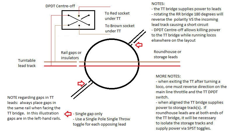
The diagram below shows how to wire a turntable without using my "stub track" solution.